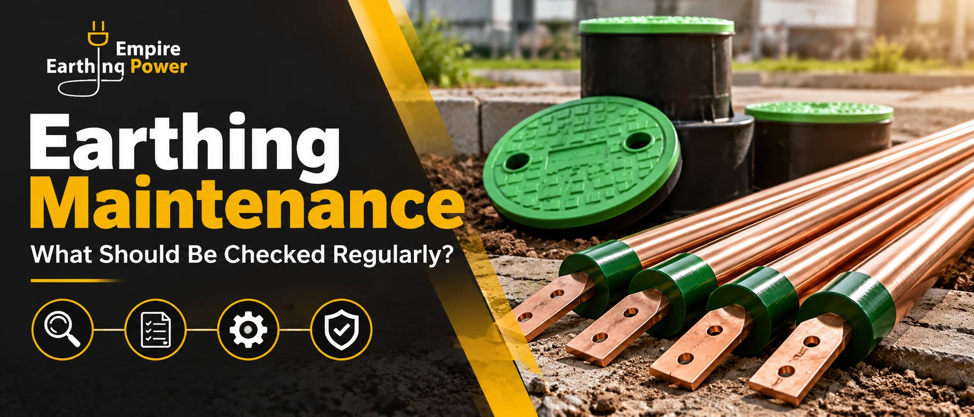
Earthing maintenance confirms that the complete protective path remains mechanically sound, electrically continuous, accessible for inspection and capable of performing as intended. It is not limited to taking one earth-resistance reading. A useful programme checks the electrode or grid, earthing conductors, bonds, joints, inspection chambers, labels, test links, surge and lightning interfaces, and the condition of equipment connections.
The answer-first rule is simple: inspect what can deteriorate, test what cannot be judged visually, compare results with the approved baseline, and investigate meaningful change before adding electrodes or chemicals. Different sites require different schedules because soil, corrosion, moisture, fault exposure, excavation, vibration and operating criticality are not the same.
Empire Earthing Power supplies several components used in grounding systems, including its earthing product category, electrodes, rods, pit covers and backfill materials. Maintenance teams should identify the exact installed products and retain their drawings and data rather than treating every earthing arrangement as interchangeable.
Why an earthing system can deteriorate
|
Change mechanism
|
What may happen
|
Evidence to check
|
|
Corrosion
|
Section loss at electrodes, conductors or joints
|
Visual condition, continuity and trend data
|
|
Loose connection
|
Higher joint resistance or intermittent continuity
|
Torque or connector inspection and thermal evidence
|
|
Soil change
|
Seasonal or long-term rise in electrode resistance
|
Comparable tests and soil/site observations
|
|
Construction activity
|
Cut, relocated or buried conductor
|
As-built comparison and continuity test
|
|
Water ingress
|
Flooded chamber, contamination or concealed damage
|
Pit inspection and drainage condition
|
|
Unauthorized modification
|
Equipment added without coordinated bonding
|
Single-line drawing and connection survey
|
A stable system can still show seasonal variation. Dry soil, a falling water table or frozen ground can increase resistance, while wet-season tests may look unusually favourable. That is why a reading should be recorded with date, weather, isolation condition, method, probe arrangement and instrument identification. Trend data collected under broadly comparable conditions is more useful than an isolated number.
Build an inventory before planning inspections
Start with the approved earthing layout, single-line diagram, lightning-protection drawing, equipment schedule and previous test reports. Number every accessible pit, test link and main earth bar. Record electrode type, conductor material and size, joint method, connected equipment and whether the point can be isolated safely for testing. If drawings are missing, create a verified survey rather than assigning labels from memory.
The inventory should distinguish the system function: protective earthing, transformer neutral, lightning protection, static control, instrumentation reference or a combined bonded network. Separate labels do not necessarily mean the electrodes are electrically isolated. Maintenance staff must understand the approved bonding philosophy before opening a test link or disconnecting any conductor.
Visual checks at earthing pits and chambers
Access, cover and identification
Confirm that each chamber can be found and opened without excavation. The cover should be intact, seated correctly and suitable for the location. Replace broken, distorted or unsecured covers before debris or traffic damages the connection. Empire describes its earthing pit cover as providing access for inspection; that access only remains useful when the chamber is labelled and kept clear.
Moisture, contamination and drainage
Look for standing water, oil, chemicals, silt, insects, roots and waste. A wet chamber is not proof of good grounding, and aggressive contamination may accelerate corrosion. Investigate the source of persistent flooding. Pumping water out immediately before a test can also change local conditions, so record what was observed and allow the engineer to interpret the result.
Electrode and test-link condition
Inspect the accessible electrode head, clamp, test link and conductor for corrosion, cracks, overheating, loose hardware, coating damage and unapproved repairs. Do not scrape, grind or recoat a component until its condition has been documented. If an electrode is copper bonded, check for damage that may expose the steel core; if it is galvanized, look for coating loss and red rust.
Checks along earthing conductors and bonds
Follow visible conductors from the electrode system to main earth bars and equipment. Look for crushed sections, tight bends, damaged insulation where used, unsupported runs, missing guards, paint over contact surfaces, corrosion at dissimilar-metal interfaces and conductors used as convenient supports. Buried routes should be compared with excavation permits and recent civil work.
Inspect bonds across doors, cable trays, structural joints, flexible connections, pipelines and equipment skids where the design requires them. Vibration and repeated opening can fatigue braids or loosen fasteners. A bond can appear present while making poor electrical contact, so suspicious joints require continuity testing under an approved isolation procedure.
Earth-resistance testing without misleading results
The selected test method must suit the system. Fall-of-potential testing can be useful when an electrode can be isolated and adequate space exists for test probes. Clamp testing may be convenient on interconnected systems but depends on a suitable parallel return path. Selective methods can separate a conductor contribution in some arrangements. Every method has limitations; the report should state them.
Before testing, record which links were opened, which parallel paths remained, the probe positions or clamp location, instrument range and recent weather. Do not disconnect a protective conductor from live equipment merely to obtain a convenient reading. Isolation, permits and temporary protective arrangements must be planned by competent personnel.
How to interpret a changed reading
A higher value may result from drier soil, a damaged electrode, a loose joint, altered test geometry, changed parallel paths or an instrument issue. Repeat the measurement only after checking the setup; do not keep moving probes until a preferred number appears. Compare the result with previous tests, design criteria and measurements at related points. A lower value can also be suspicious if a new metallic service has unintentionally created a parallel path.
Continuity and bonding tests
Continuity testing checks the low-resistance metallic path between selected points. Leads should be nulled or compensated, contact surfaces prepared appropriately, and the test current and method recorded. Large networks may need a planned set of reference points rather than arbitrary checks. A result should be evaluated against conductor length, material, joint count and baseline—not a universal value copied from another site.
Where a joint shows abnormal resistance, inspect both mechanical and environmental causes. Retightening may be inappropriate for a corroded connector or a joint designed for one-time compression. Replace components using compatible materials and the approved method. Photograph the repaired joint and update the maintenance record.
Inspection frequency should be risk based
|
Site condition
|
Reason for closer attention
|
Possible maintenance response
|
|
Critical process or high fault consequence
|
Failure affects safety or production continuity
|
More frequent inspection and trend review
|
|
Corrosive or coastal environment
|
Accelerated material loss
|
Material-focused checks and shorter intervals
|
|
Dry or highly seasonal soil
|
Large resistance variation
|
Comparable seasonal measurements
|
|
Frequent excavation or expansion
|
Higher probability of conductor damage
|
Post-work survey and continuity checks
|
|
Lightning-exposed facility
|
Surge events may damage joints or devices
|
Event-triggered inspection and coordinated review
|
Create a calendar that combines routine visual inspection, periodic electrical testing and event-triggered checks. Events may include a major fault, lightning strike, electrical shock report, unexplained protection operation, building extension, trenching near buried conductors, transformer replacement or a sudden change in monitoring data. Manufacturer instructions, statutory requirements and the site electrical-safety programme take priority over a generic interval.
What should be recorded at every maintenance visit
- Unique pit or connection identifier and exact location.
- Date, time, weather, recent rainfall and visible soil or chamber condition.
- Electrode, conductor, clamp, test link, chamber and label condition.
- Test method, instrument make/model, calibration status and lead arrangement.
- Isolation state, remaining parallel paths and any safety limitations.
- Raw readings, corrected readings where applicable and acceptance basis.
- Photographs before and after corrective work.
- Named action owner, due date and verification result.
Use the same naming convention across drawings, test sheets and field labels. A spreadsheet containing “pit 1” is unreliable when several buildings each have a pit 1. Location-based IDs and a marked plan make trend analysis and future fault investigation much faster.
Corrective actions after a failed or deteriorating result
Repair the diagnosed defect first
If testing identifies a loose clamp, broken conductor, damaged test link or flooded chamber, correct that fault and retest. Adding another electrode without repairing the open connection can hide the real problem. Where corrosion is widespread, review material compatibility and the environment rather than replacing one visibly damaged part.
Review soil and electrode design before adding material
Backfill can be part of an engineered electrode installation. Empire lists a back fill earthing compound, but maintenance teams should not pour unverified material into a pit as a routine way to lower readings. Confirm compatibility, quantity, installation method, environmental requirements and whether the existing electrode arrangement needs redesign.
Extend the system only with approved design
Additional rods or electrodes require appropriate spacing, conductor sizing, joint design, utility clearance and updated drawings. A related copper bonded earthing rod may be suitable for some projects, but rod type and depth should follow soil data and the earthing objective. Very close rods can have overlapping resistance areas and deliver less improvement than expected.
Common maintenance mistakes
Frequent mistakes include judging a system only by one resistance reading, testing during the wet season every year without noting conditions, opening links without understanding parallel paths, leaving chambers unlabelled, using salt or water as an informal fix, accepting a handwritten certificate with no method, and failing to update drawings after new equipment is bonded.
Another mistake is treating “maintenance-free earthing” as inspection-free. The term may describe an electrode or backfill concept, but accessible joints, conductors, pits, labels and system performance still need verification. Review product details against the actual installation and keep independent test evidence.
Using condition data without losing field context
Large plants may combine periodic tests with fixed or portable monitoring of neutral current, leakage, lightning-event counters, surge-protection status or selected bonding points. Monitoring can reveal when an investigation is needed, but it does not replace inspection of pits, conductors and joints. Alarms should have a documented response, sensible thresholds and a responsible owner; otherwise they become ignored data.
Link condition data to maintenance history and plant changes. A step change after a new transformer, cable route or production line may reflect the altered network rather than electrode deterioration. Time-synchronize events where possible and preserve the original readings. The engineer should interpret the pattern using the current single-line diagram, protection settings and verified field condition.
Worked example: rising resistance at a factory pit
A factory records a gradual rise at one labelled electrode over three annual tests. The maintenance team first confirms that the same method and test direction were used. Inspection reveals a frequently flooded chamber and green corrosion around the conductor clamp. Continuity from the test link to the main earth bar is also higher than at comparable points.
The team isolates the circuit under an approved permit, replaces the incompatible corroded connection, improves chamber drainage and documents the electrode-head condition. Testing is repeated after the repair using the recorded setup. Only if the result still fails the project criterion does the engineer review soil data and an extension design. The sequence prevents an unnecessary new rod from being installed beside a defective joint.
Procurement checklist for replacement components
Specify electrode or rod construction, length, diameter, coating or copper bond, conductor material and size, connector type, pit cover duty, test link, corrosion protection, accessory compatibility, documentation and delivery quantity. Ask suppliers to identify exclusions and assumptions. Confirm that the proposed replacement can connect to the existing system without creating a dissimilar-metal or dimensional problem.
Empire Earthing Power describes its manufacturing and product scope on its About Us page. Buyers should still request the exact current datasheet and project-specific evidence for the item offered; general company claims should not be treated as model-level approval.
A practical earthing maintenance workflow
- Verify the asset register, drawings and previous results before visiting the field.
- Plan isolation, permits, test method and safe access.
- Inspect chambers, electrodes, conductors, joints, bonds and labels.
- Test with a method suited to the system and record all conditions.
- Compare with the approved baseline and investigate meaningful change.
- Complete corrective work, retest and close the action with evidence.
- Update drawings, records and the next inspection date.
Frequently Asked Questions
1. What is included in earthing maintenance?
It includes visual inspection, continuity and resistance testing where applicable, checking conductors and bonds, maintaining access, reviewing trends and verifying repairs. The responsible electrical engineer should set the final method, interval and acceptance criteria from the approved design, site risk and applicable requirements.
2. How often should an earthing system be tested?
The interval depends on risk, environment, system purpose, operating history and applicable requirements; critical or corrosive sites may need closer attention. The responsible electrical engineer should set the final method, interval and acceptance criteria from the approved design, site risk and applicable requirements.
3. Is an earth-resistance reading enough?
No. It does not by itself prove conductor continuity, bonding quality, joint condition, touch-voltage control or correct protection coordination. The responsible electrical engineer should set the final method, interval and acceptance criteria from the approved design, site risk and applicable requirements.
4. Why does earth resistance change with the season?
Soil moisture, temperature and groundwater can change soil resistivity, so results should record conditions and be compared carefully. The responsible electrical engineer should set the final method, interval and acceptance criteria from the approved design, site risk and applicable requirements.
5. Can a clamp meter test every earthing electrode?
No. Clamp testing needs a suitable closed loop or parallel return path, and its result can be misleading when the network does not meet that condition. The responsible electrical engineer should set the final method, interval and acceptance criteria from the approved design, site risk and applicable requirements.
6. Should salt or water be added to improve an earth reading?
Routine addition can be temporary, corrosive or environmentally unsuitable. Investigate the cause and use only an approved engineered solution. The responsible electrical engineer should set the final method, interval and acceptance criteria from the approved design, site risk and applicable requirements.
7. What should be checked inside an earthing pit?
Check the cover, label, access, drainage, contamination, electrode head, clamp, conductor, test link, corrosion and mechanical damage. The responsible electrical engineer should set the final method, interval and acceptance criteria from the approved design, site risk and applicable requirements.
8. When is an event-triggered inspection needed?
Useful triggers include a major fault, lightning event, shock complaint, excavation, electrical expansion or an unexplained change in test results. The responsible electrical engineer should set the final method, interval and acceptance criteria from the approved design, site risk and applicable requirements.
9. Can two test reports be compared directly?
Only when the method, isolation, parallel paths, probe arrangement, instrument and site conditions are sufficiently comparable. The responsible electrical engineer should set the final method, interval and acceptance criteria from the approved design, site risk and applicable requirements.
10. What causes a loose earthing connection?
Vibration, poor installation, thermal cycling, corrosion, mechanical impact and incompatible hardware can all contribute. The responsible electrical engineer should set the final method, interval and acceptance criteria from the approved design, site risk and applicable requirements.
11. Does maintenance-free earthing require no checks?
No. The overall system still has accessible conductors, joints, chambers, bonds and performance that require inspection. The responsible electrical engineer should set the final method, interval and acceptance criteria from the approved design, site risk and applicable requirements.
12. What documents should be retained?
Keep drawings, product data, test setup, raw readings, photographs, repair records, instrument information and approval of acceptance criteria. The responsible electrical engineer should set the final method, interval and acceptance criteria from the approved design, site risk and applicable requirements.
Keep the Protective Path Visible, Testable and Ready
A dependable earthing system is maintained through traceable inspections, comparable tests and corrective work aimed at the real defect. Empire Earthing Power can help identify compatible electrodes, rods, pit covers and earthing materials for an approved repair or extension. Share the system purpose, drawings, soil information, current readings, photographs and required quantities through the Empire Earthing Power contact page for a project-specific product discussion.